Field Mill Theory
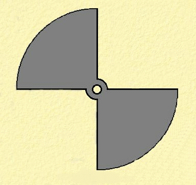
For the purposes of the following explanation, I will assume the rotor and measuring electrode are the same shape and size, with two sectors as shown right.

A static electric field of intensity E (volts/metre) incident on a plane surface of A (m2) will give rise to a surface charge Q (Coulombs) This assumes the electric field is at 90° to the plane surface. From Maxwells' equations:-
The quantities are related:- Q = E x eo x A …..(1)
If the incident E field is not at 90º, then this expression becomes
Q = E x eo x A x cos Ø
Where: Q = the surface charge in Coulombs (C)
E = incident electric field. (V/m)
eo = permittivity of free space (8.85 x 10⁻¹² F/m)
A = surface area of the plane surface (m2)
Ø = angle between the measuring surface A and the incident field E.
Due to the action of the rotating vane, the incident field E will be modulated in a sinusoidal manner :-
Q = E x sin (wt) x eo x A …..(2)
Where w = 2 x Pi x f and f = rotational frequency of the motor driven vane x 2 ( 2 vanes )
Note: The waveform generated by this shape of vane isn't truly sinusoidal but is close enough for this analysis.
Current flow in terms of charge is defined as :-
i = dQ/dt .....(3) From: Q = C x V = i x t
Differentiating (2) with respect to t :-
dQ/dt = A x E x eo x w x cos (wt) = i …..(4)
Multiplying (4) by RL :- Now the voltage (V) across RL = i x RL …..(5)
V = RL x A x E x eo x w x cos (wt) …..(6)
In practice RL , A, and eo are all constant. The rotational speed of the motor via the electronics would also be maintained essentially constant.
Thus from expression (6) we can now see that the voltage across the load resistor (V) is proportional to the electric field strength (E).


