The Field Mill Voltmeter - MK2


The photo above left shows the MK2 version of my Field Mill Voltmeter. The general construction is more rugged with an aluminium outer casing providing the main structural integrity and screening. The main electronics / signal processing boards are housed within the ABS box mounted at the rear of the main housing.
The rotary vane on this unit can be seen in more detail in the photo above left. The rotary vane comprises 4 symmetrical vanes made from brass sheet and the fixed sense electrode is of similar form. The opto coupler can be seen mounted at the top of the photo in close proximity to the rotating vane at the front of the assembly and serves to synchronise the electronics to the position of the vanes as they rotate.
The photo right shows the general mechanical construction of the Field Mill. The brass rotating vane can be seen at the top with the sense electrode / ground plane immediately below. The grey screened cable connects the sense electrode to the electronics.
The multiway ribbon connects to the optical sensor and the two way cable is the supply to the motor control pcb mounted below the ground plane. The potentiometer that sets the motor speed can be seen on the left of the motor control pcb.
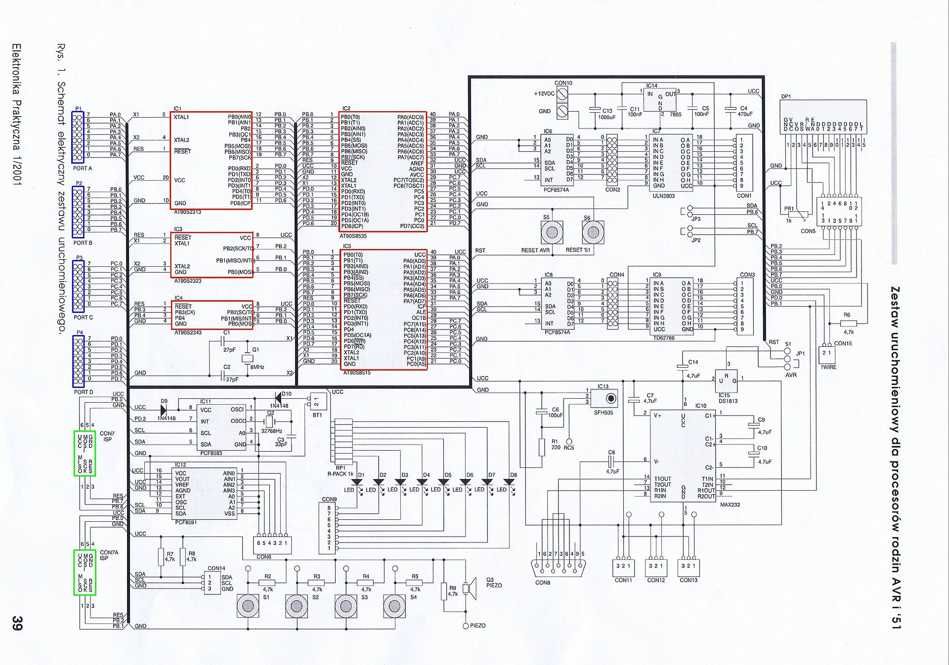
For the MK2 Field Mill schematic see bottom of the page here.
For a general guide on how to calibrate the field mill, see the Field Mill Calibration page here.
